Are you using the right product for this challenging application?
The Need for Accurate Outside Airflow Measurement in HVAC
Outside air is used to refresh the air inside modern buildings. Measuring outside air entering the building is a key factor in maintaining proper indoor air quality for occupant health and safety. It is also essential for meeting energy-savings goals and ASHRAE air quality standards required by today’s high-performance buildings. As a result, building automation systems (BAS) must take outside airflow data into account to meet ventilation standards, accurately measure energy consumption, and maintain proper indoor air quality. When building automation systems rely on technologies not specifically developed for this application, it becomes a challenge to reliably measure airflow. This can lead to increased operating costs, inadequate building pressure control, and uncomfortable or unsafe living and working conditions.
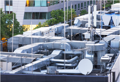

When building automation systems rely on technologies not specifically developed for this application, it becomes a challenge to reliably measure airflow.
Measurement of Outside Airflow is Difficult
Outside airflow is difficult to measure. Conditions on rooftops can be extremely turbulent, with constantly changing wind velocities and directions. This is in addition to temperature, humidity, and barometric pressure variations that can affect density. Outside air is also unfiltered and may contain moisture (fog, rain, sleet, or snow) and particulate matter. All this is made more difficult by the design of outside air inlets. These inlets do not usually have any straight duct runs to condition airflow prior to measurement.
The lack of straight duct runs to condition flow is not the only inlet design feature that makes accurate airflow measurement difficult. Inlets are often designed for multiple uses. Typically, they are used to bring air into the building to maintain indoor air quality, and at the same time, they are used as an outside air economizer inlet. This means that the inlet is oversized for maintaining indoor air quality. The result is very low flow velocities at the inlet most of the time. Low velocities directly affect measurement accuracy and reliability. Rooftop packaged units are a worst-case example, as the minimum outside air and the 100% outside air economizer functions are forced into a single inlet. To make matters worse, some manufacturers combine several unit sizes into a single box/frame/control damper/hood size. Any product chosen to provide critical airflow measurements for this tough application must overcome these issues.
The three most often used technologies in outside airflow measurement are thermal dispersion, pitot array, and the pressure difference across a known resistance. As a manufacturer of all three, Air Monitor has decades of real-world experience utilizing these solutions in various outside airflow applications. This in-the-field experience has allowed us to evaluate and compare the performance characteristics of each technology without a built-in bias. The following information outlines the pros and cons of all three approaches and Air Monitor’s recommendation for measuring outdoor airflow.
Technology #1: Thermal Dispersion
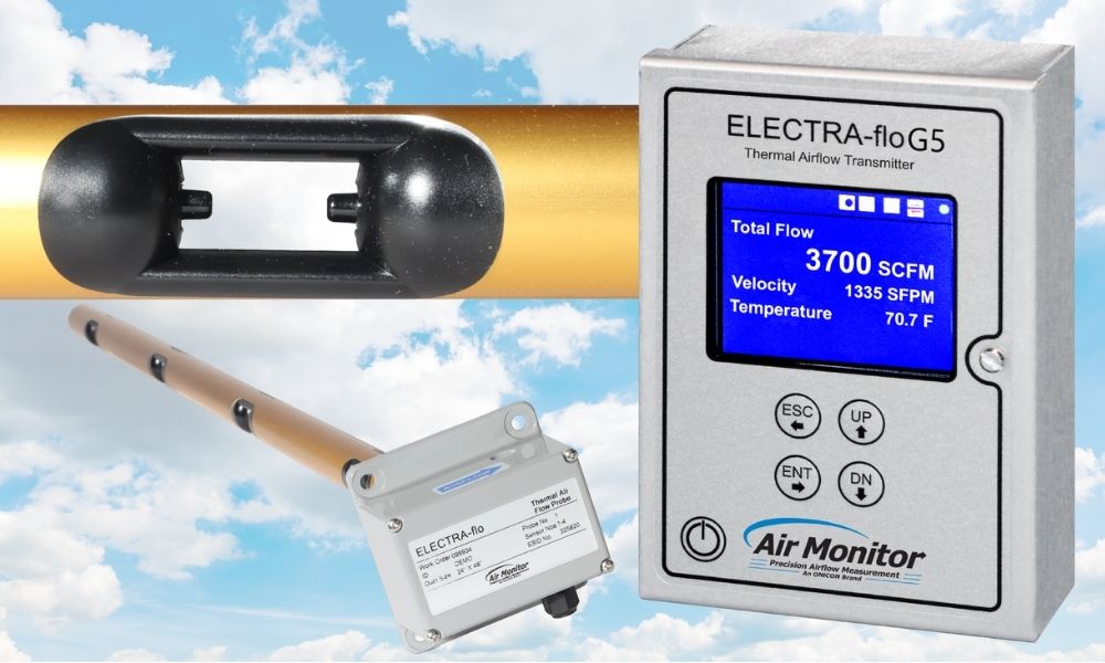
Thermal dispersion is a velocity-based technology. Velocities are measured at several distinct points and the readings are averaged. The flow rate is calculated using the average velocity and the cross-sectional area of the intake measured at the plane where the instrument is inserted (this can be difficult in hoods, with tapered inlets).
Each point of measurement utilizes two precision-matched thermistors for temperature measurement. One thermistor measures ambient airflow temperature, and the other is heated to maintain a fixed differential above the ambient temperature. Heat is transferred from the heated thermistor to the air stream, and as airflow velocity increases, the rate of heat dispersion increases. The relationship between the airflow rate and the power needed to maintain the temperature difference is used to calculate velocity.
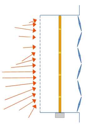
Thermal dispersion airflow measurement works best when used with upstream straight ducts to condition flow.
Pros:
- Measurement accounts for temperature and elevation; output can be either actual flow rate (ACFM) or standard flow rate (SCFM)
- High turndown – a wide range, from low to moderately-high velocities
- Mid-price range
- Sold as a system, not as component parts
Cons:
- Thermal sensors do not tolerate any form of moisture in the air
- Moisture causes sudden quenching of the heated sensor resulting in random measurement spikes and instability
- They perform poorly in dynamic and turbulent airflow conditions.
- Measurement apertures are not tolerant of airflow that is off-axis (angular flow through open wall intakes, intake hoods, and duct transitions)
- Flow elements cannot distinguish between forward and reverse direction of flow
- There is a tradeoff between the cost and the number of measurement points. This often results in fewer used than industry recommendations for accurate average velocity measurement. To make up for this, thermal dispersion systems typically require 2 to 8 diameters of straight duct runs both upstream and downstream which are rarely available in outside air intake duct configurations
- Velocity measurement is susceptible to wind gusts resulting in a very noisy signal making dampers difficult to control
- Requires regular, preventative maintenance
- The dirt and debris found in the unfiltered outside air can coat and insulate the thermal sensors causing thermal coefficients to change, resulting in inaccurate flow measurement
- The dirt and debris found in the unfiltered outside air can coat and insulate the thermal sensors causing thermal coefficients to change, resulting in inaccurate flow measurement
Technology #2: Pitot Array
Pitot-based measurement (Delta P) has been used in HVAC applications for nearly half a century. It is a velocity-based technology. Dynamic pressure and static pressure are measured at many points, and the results are averaged. The velocity of airflow is proportional to the difference in pressure. A differential pressure (DP) transmitter is used to convert the difference into an average airflow velocity. The transmitter then converts average velocity into average airflow volume using the cross-sectional area of the duct.
There are substantial differences in the performance and price level of products that use this measurement principle. Systems have two components: Pitot probes and the DP transmitter. System accuracy depends on the number of sensing points and the selection of a DP transmitter. Transmitters that offer an excellent turndown (velocity range) are much more expensive. At the low price point, we see mismatched components and systems that use fewer than the required number of probes, and a generic, low accuracy, limited turndown, DP transmitter. At the high end, we see systems with well-matched probes, and transmitters that are used as one flow measurement system. Systems of this type are performance tested and recognized by an independent test laboratory like Air Movement & Control Association International, Inc. (AMCA).
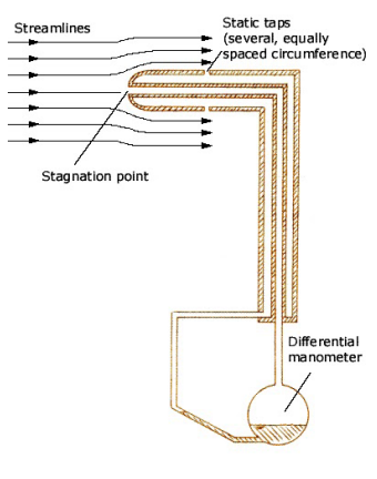
Air inlets lacking straight duct runs to condition flow require large numbers of Pitot tubes to achieve accurate flow measurements.
Pros:
- Measurement systems with correction for temperature and elevation via secondary measurements can output either actual flow rate (ACFM) or standard flow rate (SCFM)
- Low-cost systems may be acceptable depending on performance requirements
- Velocity can be measured at a vast number of points across the duct resulting in accurate average velocities
- Tolerates moisture better than thermal technologies – moderately tolerant of dust in the air
- Robust construction, no active components in the air stream improves long-term reliability
Cons:
- Over a long period of time, sensing holes can plug with accumulated dirt, requiring periodic cleaning
- Limited turndown for systems with poor transmitter selection, however with a better selection of transmitters, this can be eliminated
- These systems do not perform as well in dynamic and turbulent airflow conditions
- Measurement apertures are not tolerant of flow that is off-axis (angular airflow), some Pitot probes are designed to compensate for limited angular velocity vectors, but not all systems offer this
- Low-cost systems sacrifice performance
- If velocity is measured with far fewer measurement points than recommended by industry standard
- Can only output actual flow rate (ACFM) if secondary temperature compensation is not performed
- Periodic Calibration is required (due to transducer zero drift if the DP transmitter selected does not have AUTO-zero capability)
Technology #3: Pressure Difference Across a Known Resistance
In the late 1700s Giovanni B. Venturi observed the pressure drop that occurs when a fluid accelerates to pass through a constriction. He correlated this with Bernoulli’s work and published the Venturi Effect in 1797. Those mathematical relationships have been used in measurement technologies for over a century in pipes. Still, they are not practical for measuring outside airflow in large intake ducts primarily because they produce very high-pressure drops.
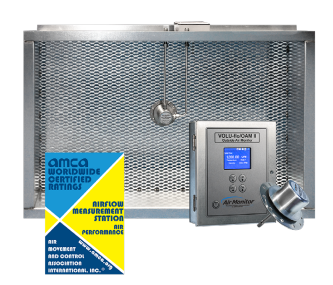
The Air Monitor OAM II Outside Airflow Measurement System utilizes these principles to measure static pressure fields that develop when air flows through any screen or louver with a known velocity vs. pressure drop curve without a significant change in the pressure drop. These static pressure measurements used in concert with temperature, barometric pressure measurements, and inlet size can be used to calculate the flow rate at any atmospheric condition.
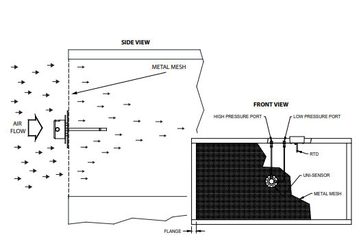
Small differences in static field pressures created by air moving through a fixed inlet allow the OAM II to accurately measure airflow without the need for straight ducts to condition flow.
Pros:
- High tolerance for dynamic variations in velocity and direction
- The system accounts for temperature, elevation, and barometric pressure; it can output either actual flow rate (ACFM) or standard flow rate (SCFM)
- Zero straight run of duct required
- High turndown capability with stacked transducer arrangements
- Reliable accuracy in real-world conditions
- Nearly impervious to dust and moisture
- Robust construction
- Versatility – can easily be applied with louvered openings, hoods, dampers, ducts, plenums, etc.
- Can be retrofitted to existing systems
Cons:
- None for outside airflow applications
The Informed Decision
Precision in outside airflow measurement is essential to ensure that ASHRAE ventilation standards are met, energy consumption calculations are accurate, and that proper indoor air quality is maintained for occupant health and safety. Each of the technologies discussed in this guide has their strengths and can be a viable solution for some airflow measurement applications. As an experienced manufacturer of all three systems, we at Air Monitor can confidently say that the pressure difference across a known resistance technology found in our OAM II product is the best airflow measurement solution for outside air applications.
Click here for more information on the Air Monitor OAM II Outdoor airflow measurement system.
